| Main Index / SCM Tutorials / Character Assembly |
|
| |
|
This tutorial will show you how to extend the Zipping process described in the previous tutorial to the task of attaching legs to an animal's body. Once the body is properly assembled, SurfaceContinuityManager+ will be able to hold all of the surfaces together seamlessly during animation and rendering. To begin the tutorial, load the scene scm-tutlegs. (This comes in a zip file from the SCM Tutorials page.)
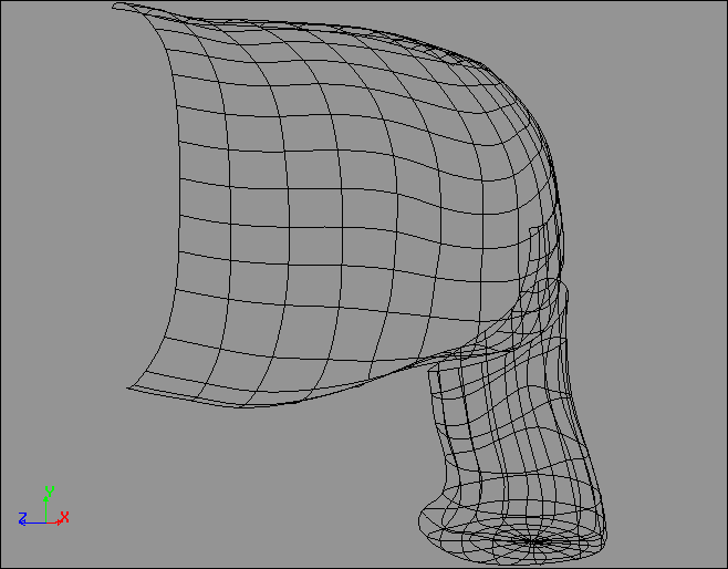
At the starting point, the body and the leg are two separate objects with gaps between them. Their edges do not face each other, so they cannot be zipped together as the grids were in the previous tutorial. SurfaceContinuityManager+ will only be able to hold them together if they have rows of points already aligned in matching positions, a situation that does not exist yet.
While this may seem counter-intuitive, the first step towards unifying these surfaces with the Surface Continuity Manager is to start by further dividing them. The leg will need to be cut into 4 slices, and the body will need to be cut into 8 rectangular surfaces, in order to expose compatible edges that can be zipped together.
1. Select the body and Draw>Cut along the vertical curve immediately in front of the leg, as shown below.
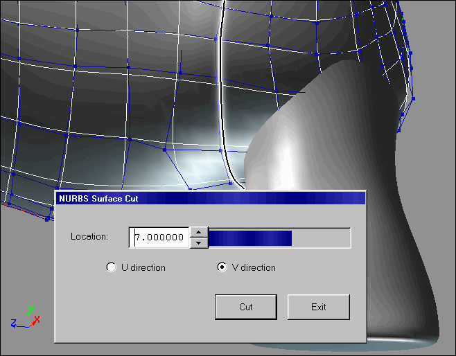
2. Draw>Cut again immediately behind the leg, at the Location of 3 in the V direction.
3. Cut the 3 resulting columns into 3 sections each, with horizontal cuts above and below the leg. These cuts will fall at the Locations of 1 and 5 in the U direction.
4. Because the Cut function does not delete the original (uncut) models, there will now be several overlapping models in the same place. By selecting nodes in the Schematic window, delete all the larger body surfaces except for the nine squares. Also delete the middle of the nine squares, so that an opening appears above the leg, as shown below.
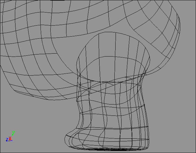
5. Select the leg, and use Draw>Cut to divide it into 4 slices. The cuts should align with the corners of the square opening in the body surface. The cuts will fall at the Locations of 0, 4, 8, and 12 in the V direction. Use the schematic window to delete all overlapping leg sections other than the four quarters.
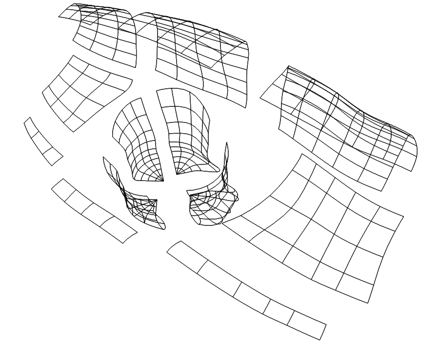
As an illustration, this exploded view shows the 12 surfaces separated to show where they have been cut. Check to make sure that you have cut the models into all of the separate surfaces shown. Your results so far should match the models in the hierarchy named "Cut."
6. Multi-Select the outside panel of the leg, and the body surface immediately above it. Double-check that the two surfaces are ready for zipping by turning on Show>Edge Flags, and checking that the colored edges indicate the same directions on both surfaces. For example, if the body segment is green on the right and red on the bottom, then the leg segment should be green on the right and red on the bottom. If the edge flags do not match, single-select the leg surface only, and use Effect>Curve Controls to Swap U and V, Inverse U, or Inverse V.
7. Check that both of the surfaces have the same number of points running across the edge where they meet. If not, add or delete points as needed to make the point-counts match.
NOTE: If you add or delete any points, use the function Effect>Reparamerization afterwards, and set all of the surfaces back to a uniform parameterization.
8. With the two surfaces Multi-Selected as shown below, choose Draw>Zip Surfaces. Click the lower left corner of the selected body surface, and choose the horizontal row of points running along the bottom. Next click the upper left corner of the selected leg surface, and choose the horizontal row of points running along the top. Connect all of the points with the Zip Surfaces dialog as shown below.
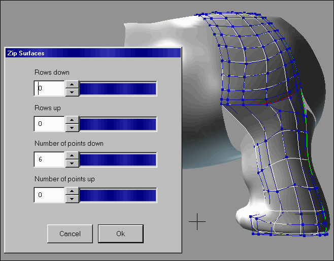
NOTE: If Zip Surfaces fails to work as shown, it is because the two surfaces were not properly matched in steps 6 and 7. Use Info > Selection to verify that they truly have the same number of points running along their shared edge, instead of just counting the points by sight. Sometimes cutting NURBS surfaces produces situations where two rows of points can overlap near an edge, effectively hiding a row of points from you.
9. For the three other quarters of the leg, repeat the process of steps 6 through 8, zipping each leg segment to the body surface immediately above it.
NOTE: After you have completed this step, your results should match the models in the hierarchy named "Zipped."
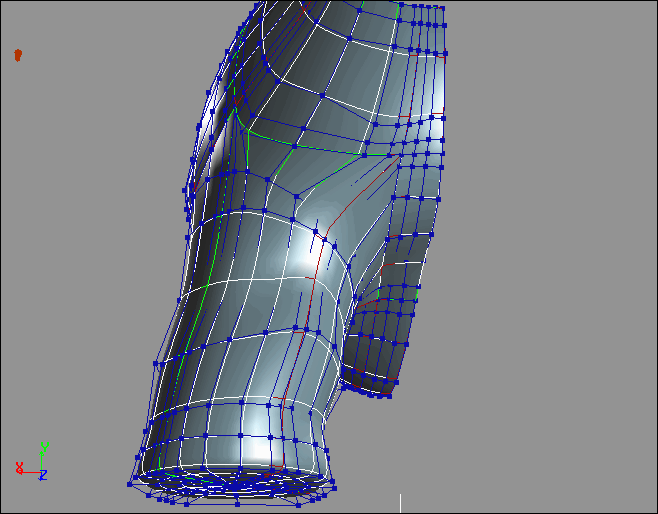
10. Select all of the surfaces in the half-body and the leg, and choose Effect>Symmetry over the YZ Plane (X=0).
11. Your surfaces are finally ready for the SurfaceContinuityManager+! With all of the surfaces multi-selected, choose Deformation > SurfaceContinuityManager+ and click OK.
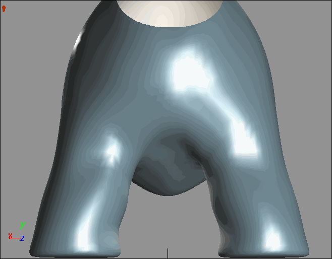
This process of attaching legs to a body has introduced a basic technique of seamless stitching, which is extensible to many other modeling tasks. No matter what the shape of the surfaces, similar patterns can be assembled again and again, so that the steps followed in this tutorial would be applicable to many other modeling situations.
The Pattern
Viewed as flat surfaces, the basic pattern that was followed for attaching a leg could be seen as follows:
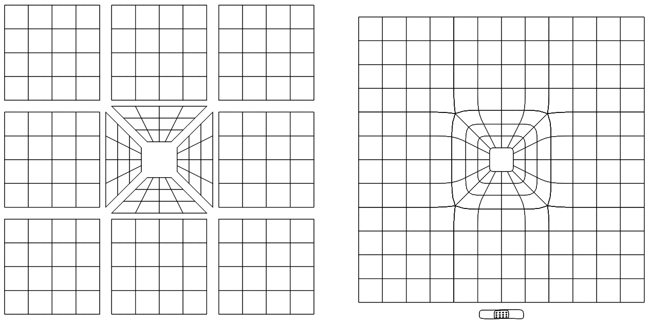
The center four surfaces of this pattern were the four quarters of a leg in this tutorial. This is a useful pattern that recurs many times in NURBANA models. The next tutorial uses the same basic pattern to insert an eye into the surface of a head.
SCM Tutorials | >>> Next Tutorial >>>
|
This tutorial copyright © 1999 by Jeremy Birn. Please do not duplicate any part fo this tutorial without written permission. |